Description
Applications:
|
|
Features:
|
|
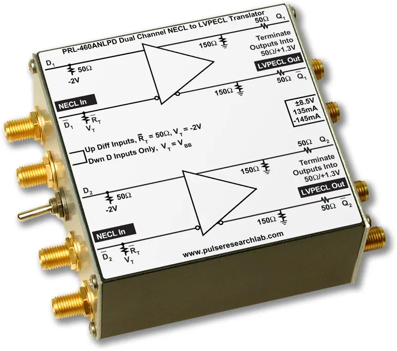
DescriptionThe PRL-460ANLPD is a dual channel NECL to LVPECL Logic Level Translator module, intended for operation from DC to the GHz range. Maximum clock frequency is typically 1.5 GHz. These modules can receive either single-ended or differential input signals, to be selected by a switch. The complementary outputs of these modules are designed for driving 50 Ω loads terminated to +1.3 V, and they can also drive AC coupled or floating 50 Ω loads. These high speed translator modules facilitate testing and integration of high speed digital communications circuits and systems, where conversion of signals from NECL to LVPECL logic families is often required The PRL-460ANLPD is designed to interface with NECL circuits operating with a -5.2 V or -3.3 V supply. In the differential input mode, both inputs D and D of the PRL-460ANLPD are terminated into 50 Ω/-2 V. In this mode, either one or both inputs can accept AC coupled signals as well. In the single input mode, signals should be connected to the D inputs only. The D inputs are switched internally to VBB, nominally -1.3 V. The termination resistors, RT, for the D input channels are changed to 62 Ω. A block diagram of the PRL-460ANLPD is shown in Fig. 1. The PRL-430LP complementary outputs must be used together for driving differential LVPECL inputs only, because the reduced output logic swing of 400 mVPP (for short circuit protection reasons) is not logic level compatible with some single-ended LVPECL inputs. The PRL-460ANLPD is supplied with a ±8.5 V AC/DC Adapter and housed in a 1.3 x 2.9 x 2.9-in. extruded aluminum enclosure. |
 Fig. 1 PRL-460ANLPD Block Diagram
(0° C ≤ TA ≤ 35° C)*
| Symbol | Parameter | PRL-460ANLPD | Unit | ||
|---|---|---|---|---|---|
| Min | Typ | Max | |||
| RIN | Input Resistance | 49.5 | 50.0 | 50.5 | Ω |
| ROUT | Output Resistance | 49.5 | 50.0 | 50.5 | Ω |
| VTT | “D” Input Termination Voltage (fixed) | -2.2 | -2.0 | -1.8 | V |
| VT1 | “D” Input Termination Voltage | -2.2 | -2.0 | -1.8 | V |
| VT1 | “D” Input Termination Voltage (variable) | -1.17 | -1.30 | -1.43 | V |
| VOL | Output Low Level | 1.25 | 1.40 | 1.55 | V |
| VOH | Output High Level | 1.70 | 1.85 | 2.00 | V |
| VOPP1 | Output Voltage Swing, f ≤ 550 MHz | 400 | mV | ||
| VOPP2 | Output Voltage Swing, f ≤ 700 MHz | 280 | mV | ||
| IDC1 | DC Input Current, +8.5 V | +125 | +135 | mA | |
| IDC1 | DC Input Current, -8.5 V | -138 | -145 | mA | |
| VDC | DC Input Voltage | ±7.5 | ±8.5 | ±12 | V |
| VAC | AC/DC Adapter Input Voltage | 103 | 115 | 127 | V |
| tPLH | Propagation Delay to output ↑ | 1.25 | ns | ||
| tPHL | Propagation Delay to output ↓ | 1.25 | ns | ||
| tr/tf | Rise/Fall Times (20% – 80%)* | 600 | 850 | ps | |
| tSKEW | Skew between any 2 outputs | 50 | 120 | ps | |
| fmax | Max Clock Frequency | 1.25 | 1.50 | GHz | |
| Size | 1.3 x 2.9 x 2.9 | in. | |||
| Weight excluding AC adapter | 7 | Oz | |||
| Shipping weight including AC adapter | 4 | lb. | |||
* An unused complementary output must be either terminated into 50 Ω/VTT or AC coupled into a 50 Ω load; otherwise, output waveform distortion and rise time degradation will occur. Use the PRL-ACT-50 dual channel AC coupled 50 Ω Termination for terminating unused complementary outputs and the PRL-SC-104 DC Block or a 12dB AC coupled attenuator for connection of LVPECL signals to 50 Ω input oscilloscopes, if DC information is not needed. Otherwise, use the PRL-550NQ4X four channel LVPECL Terminators for the 50 Ω/VTT termination and for connection of LVPECL signals to 50 Ω input oscilloscopes.

Explore more from our collection.

Reviews
There are no reviews yet.