Description
Applications:
|
|
Features:
|
|
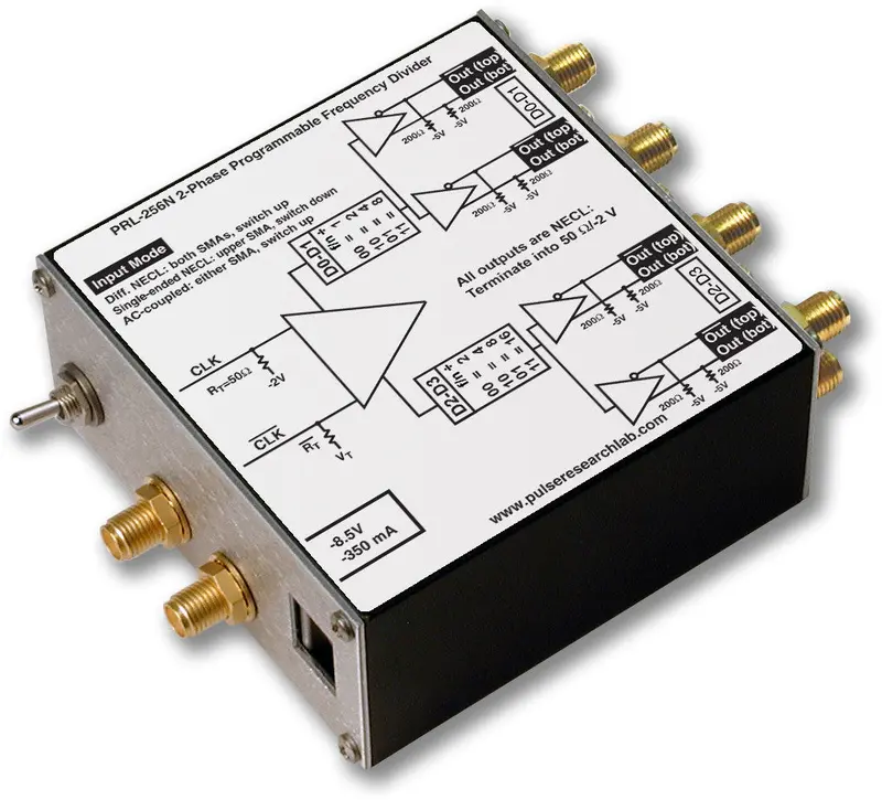
DescriptionThe PRL-256N is a NECL input, manually programmable, two-phase frequency divider with four pairs of complementary NECL outputs, capable of running at input frequencies in excess of 2 GHz. The input selector switch selects either single-ended or differential inputs. In the differential input mode, both inputs CLK and CLK are terminated internally into 50 Ω/VTT, where VTT is equal to -2 V for NECL, and therefore, either one or both inputs can accept AC coupled signals as well. In the single input mode, input signals should be connected to the CLK input only. The CLK input is internally switched to VBB, nominally -1.3 V for NECL, and input resistor RT for the CLK input channel is changed to 62 Ω. The input buffer is followed by two banks of independent manually programmable dividers, Φ1and Φ2. The input is divided by 1, 2, 4, or 8 for the Φ1 bank via D0 and D1 of a two-bit DIP switch. It is divided by 2, 4, 8 or 16 for the Φ2 bank via D2 and D3 of a second two-bit DIP switch. Each bank has two pairs of complementary outputs. All outputs are synchronous with the input frequency and are square waves (50% duty cycle) except for the f/1 outputs, which follow the input. The outputs are suitable for driving long lines terminated into 50 Ω/-2 V or AC-coupled 50 Ω loads. The PRL-256N is ideal for applications where a high-frequency divider or pre-scalar is needed for triggering or down-sampling. The two phases of output enable applications requiring two different ratios from a common reference frequency, and the 1:2 fanout feature enables system synchronization and monitoring/triggering applications from a single reference clock source. Applications for the PRL-256N include data acquisition, test, measurement, R&D, and system integration. The unit includes an AC adapter for ready-to-use convenience on the bench or in a system. All I/O connectors are SMA. The extruded aluminum housing is suitable for mounting with the optional brackets. |

PRL-256N Block Diagram
SPECIFICATIONS (0° C ≤ TA ≤ 35° C)*
| Symbol | Parameter | PRL-255N | Unit | Comments | ||
|---|---|---|---|---|---|---|
| Min | Typ | Max | ||||
| RIN | Input Resistance | 49.5 | 50 | 50.5 | Ω | |
| VTT | D Input Termination Voltage (fixed) | -2.2 | -2 | -1.8 | V | CLK input |
| VT1 | D Input Termination Voltage (switch Up) | -2.2 | -2.0 | -1.8 | V | CLK input |
| VT2 | D Input Termination Voltage (switch Down) | -1.17 | -1.30 | -1.43 | CLK input | |
| VIL | Input Lo Voltage | -1.95 | -1.60 | -1.48 | V | |
| VIH | Input Hi Voltage | -1.13 | -0.90 | -0.81 | V | |
| SW VIN | Sine wave Input, VPP | 30 | 50 | 500 | mV | |
| VOL | Output Lo Voltage | -1.95 | -1.70 | -1.48 | V | |
| VOH | Output Hi Voltage | -1.13 | -0.90 | -0.81 | V | |
| IDC | DC Input Current | -375 | -350 | mA | ||
| VDC | DC Input Voltage | -12 | -8.5 | -7.5 | V | |
| VAC | AC/DC Adapter Input Voltage | 103 | 115 | 127 | V | |
| tPLH | Propagation Delay to output ↑ | 2500 | ps | |||
| tPHL | Propagation Delay to output ↓ | 2500 | ps | |||
| tr/tf | Rise/Fall Times (20%-80%) | 200 | 300 | ps | ||
| tSKEW1 | Skew ↔ Φ1 or Φ2 outputs | 40 | 120 | ps | ||
| tSKEW2 | Skew ↔ Φ1 and Φ2 outputs | 40 | 120 | ps | D0/D1=10, D2/D3=00 | |
| tSKEW | Skew between any two outputs | 40 | ps | |||
| FMAX | Max clock frequency | 2.0 | 2.5 | GHz | ||
| Size | 1.3 x 2.9 x 2.9 | in. | ||||
| Weight, excl. AC adapter | 5 | Oz. | ||||
| Shipping weight, incl. AC adapter | 4 | lb. | ||||
* All measurements are made with outputs terminated into 50 Ω/VTT.
Notes:
The output rise and fall times are measured with with all inputs terminated into 50 Ω/VTT. For best performance all outputs should be terminated into 50 Ω/VTT or else AC- coupled into 50 Ω loads. If a single output is used, its complement must be terminated; otherwise output waveform distortion will occur. If one pair of complementary outputs is used, the other complementary pair may remain unterminated. Use the PRL-550 Series, four channel ECL/PECL/LVPECL Terminators, for the 50 Ω/VTT termination and for connection of ECL/PECL/LVPECL signals to 50 Ω input oscilloscopes. The PRL-ACT-50, Dual Channel AC-Coupled 50 Ω Terminator, may also be used to provide the 50 Ω/VTT termination. If preservation of DC levels is not required, then the PRL-SC-104, 0.1 µf DC block or a 12 dB AC-coupled attenuator, may be used to connect the NECL/PECL/LVPECL outputs to 50 Ω input instruments.
PDF Datasheet
Explore more from our collection.
Reviews
There are no reviews yet.